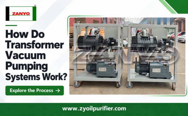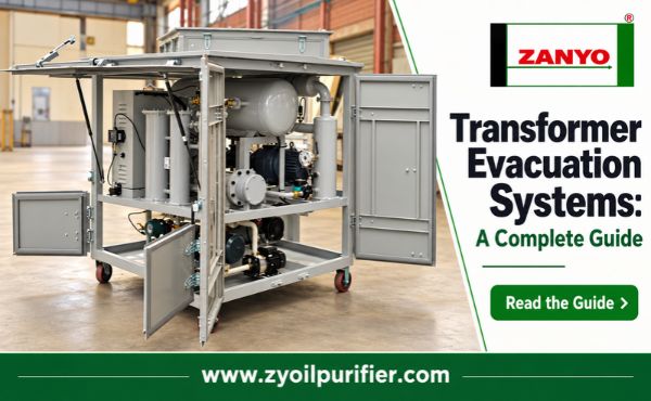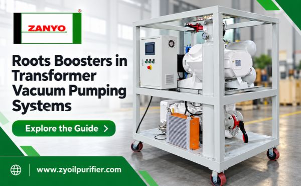
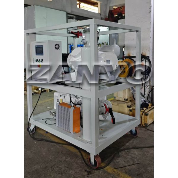
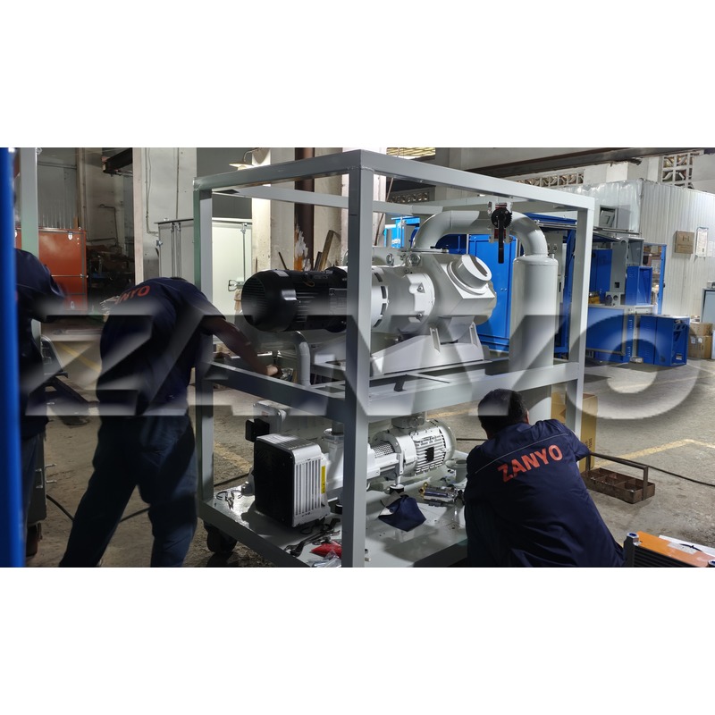
Roots boosters increase gas-handling capacity and effective pumping speed in transformer vacuum pumping systems after suitable inlet and outlet conditions are established. They use two synchronized, non-contacting lobes to transfer gas from transformer sides toward backing pumps. Because Roots boosters provide little internal compression, they normally cannot discharge directly from deep vacuum to atmospheric pressure. They must operate as part of correctly matched pump trains.
This distinction matters during equipment selection. Roots boosters can shorten evacuation time when pump speed is the true limitation, but they cannot compensate for leaking transformer tanks, narrow hoses, restricted valves, wet insulation, or undersized backing pumps.
How Roots Boosters Move Gas
Inside Roots boosters, two symmetrical lobes rotate in opposite directions. Timing gears keep the lobes synchronized so that they pass close to each other and the housing without contact. Gas entering through inlet ports becomes trapped between the lobes and casing, moves around the chamber, and is released at outlet ports.
The pumping chamber does not rely on sliding contact or liquid seals to move gas. This allows high rotational speeds and high pumping capacity. However, the pumps still contain bearings, gears, shaft seals, drives, and lubrication systems that need correct operation and maintenance.
Roots boosters do not substantially compress trapped gas inside their chambers. Pressure rises when transferred gas meets the higher pressure at outlets. The resulting pressure difference creates heat and load. If this difference becomes excessive, motors can overload and pumps can overheat or suffer mechanical damage.
Backing pumps solve this problem by accepting gas from booster outlets and compressing it toward atmospheric discharge. The two pumps therefore perform different but connected jobs.
Why Transformer Systems Combine Two Pump Stages
At the beginning of transformer evacuation, gas density and mass flow are high. Backing pumps are suited to starting from atmospheric pressure and removing this initial load. Depending on the booster design and control method, backing pumps may operate alone until transformer pressure falls sufficiently.
When Roots boosters begin contributing, they increase the volume of gas delivered to backing pumps. As pressure falls, backing-pump performance alone may become slower, while boosters can maintain strong pumping speed across the selected lower-pressure range.
This does not mean every two-pump package is properly matched. The backing pump must accept the booster discharge without allowing excessive outlet pressure. Engineers assess pumping-speed curves, expected gas load, pump ratio, permissible differential pressure, cooling, and control strategy together.
| Pump-train stage | Main equipment | Main purpose |
|---|---|---|
| Initial evacuation | Backing pump | Remove high initial air load and reduce pressure safely |
| Booster operating range | Backing pump plus Roots booster | Increase throughput and effective pumping speed |
| Treatment or hold stage | Pump train or isolated tank, according to procedure | Maintain conditions or evaluate pressure behavior |
The changeover point is equipment-specific. Publishing one universal start pressure would be misleading because permitted conditions depend on booster design, motor control, bypass arrangement, and backing-pump capability.
Three Common Booster Control Strategies
Pressure-controlled delayed starting is a straightforward method. Backing pumps start first, and Roots boosters start after inlet pressure reaches a set condition. This limits differential pressure during early evacuation. Reliable gauges, correct settings, and functioning interlocks are essential.
Variable-frequency control allows booster speed to change with operating load. Boosters may start earlier at reduced speed and accelerate as pressure conditions improve. This can produce smoother pump-down and help control motor current and temperature, but sensors and programming must be correctly commissioned.
Differential-pressure bypass systems provide another approach. When inlet-to-outlet pressure difference exceeds the permitted level, bypass valves allow gas to move around booster stages or limit the load. Some booster designs can operate across wider pressure ranges using this arrangement. Bypass condition, capacity, and maintenance should be included in equipment reviews.
What Roots Boosters Can Improve
Roots boosters can improve pump-down time when evacuation systems are limited by available pumping speed at lower pressures. This is particularly relevant for larger connected tank volumes, repeated service work, limited outage windows, or processes with sustained gas and vapor loads.
They may also improve the ability of systems to maintain useful pumping speed as backing pumps approach the lower-pressure part of their performance curves. In a balanced system, this means faster movement through the part of evacuation that would otherwise consume disproportionate time.
However, boosters cannot guarantee a particular final pressure at transformer tanks. Their performance is transmitted through manifolds, hoses, valves, and transformer connections. If these components have poor conductance, much of the additional pump capacity is lost before it reaches the tank.
Boosters also do not directly solve moisture diffusion. Vacuum encourages surface moisture to evaporate, but water held deeper inside cellulose must migrate outward before pumps can remove it. Adding booster capacity may remove available vapor faster without proportionally reducing the time required for moisture to leave solid insulation.
Decide Whether Booster Capacity Addresses the Real Constraint
Before specifying Roots booster transformer vacuum systems, buyers should identify the current bottleneck. Four possibilities account for many slow evacuation problems:
- Pump-speed limitation: Pressure responds normally, connections are adequate, and additional speed would shorten the lower-pressure stage.
- Conductance limitation: Pump-side pressure is much lower than transformer-side pressure because hoses, ports, or valves restrict flow.
- Leakage limitation: Incoming air creates a continuing load and pressure rises significantly after isolation.
- Vapor or outgassing limitation: Moisture and gas continue leaving internal materials even when external leakage is controlled.
Only the first condition is solved directly by adding pumping speed. Larger boosters connected through the same narrow hoses may produce little improvement. Leakage should be repaired, while vapor-dominated processes may require controlled heat, more treatment time, or another approved drying method.
How to Match Roots Boosters and Backing Pumps
Selection begins with transformer volume, required pressure range, permitted process time, expected vapor load, and available connection size. Suppliers should then demonstrate how both pumps perform across the relevant range—not only provide maximum flow or ultimate vacuum figures.
Important questions include:
- What are the pumping-speed curves for the complete pump train?
- What booster-to-backing-pump ratio is used, and why?
- What is the maximum permitted differential pressure across the booster?
- Does the system use delayed start, variable speed, bypass control, or a combination?
- Which instruments trigger starting, speed reduction, alarms, and shutdown?
- How are reverse flow, oil migration, overheating, and power loss controlled?
- Where are pressure measurements taken?
Connection design should be reviewed at the same time. Short, large-diameter lines generally deliver more effective pumping speed than long flexible hoses. Pumps should not be upsized without checking manifolds, transformer ports, and valves.
Conclusion
Roots boosters are valuable because they add pumping speed where backing pumps may become slow, not because they independently solve every vacuum problem. Effective systems match booster and backing-pump performance, protect permitted pressure difference, preserve line conductance, and measure pressure where it matters.
Before adding boosters, identify whether evacuation is limited by pumps, connections, leakage, or moisture release. That diagnosis prevents unnecessary capacity, improves equipment selection, and produces more predictable transformer evacuation times.