Transformer evacuation systems are integrated pump packages used to remove air and water vapor from sealed transformer tanks before vacuum filling, after assembly, or during approved maintenance and drying procedures. Correct systems are selected from transformer volume, permitted vacuum, required process, available treatment time, connection layout, and site conditions—not simply from the largest advertised pump capacity.
Buyers should convert field requirements into duty specifications that define performance at transformer connections and explain how results will be verified.
Main Transformer Evacuation System Configurations
Single-pump systems use backing or roughing pumps to remove air and achieve the specified operating pressure. They offer simple controls, compact layouts, and fewer service components. They can be suitable when transformer volumes, pressure requirements, and maintenance windows do not demand additional pumping speed.
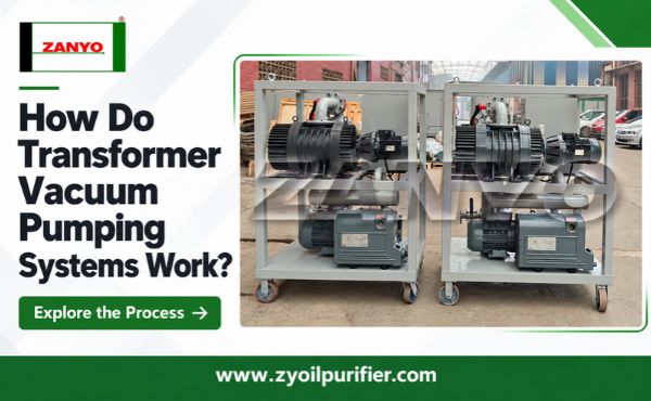
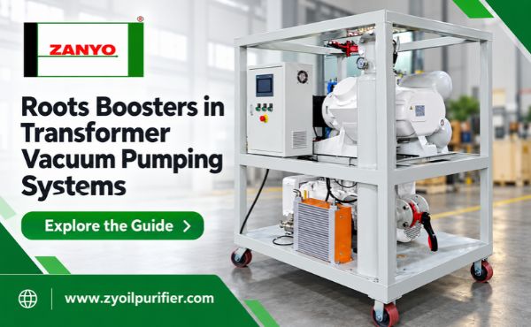
Booster-assisted systems combine backing pumps with Roots boosters. Backing pumps manage early evacuation and booster outlet pressure, while boosters increase gas throughput in their suitable pressure range. Proper matching is essential: boosters that deliver more gas than backing pumps can accept may experience excessive pressure difference, temperature, or motor load.
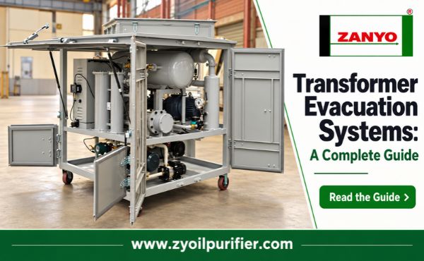
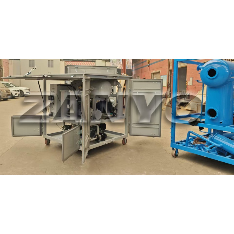
Packages can be portable, skid-mounted, containerized, or trailer-mounted. Portability is useful for service fleets, but the mounting style also affects weather protection, connection time, noise control, electrical distribution, lifting, transport, and access for maintenance.
| Configuration | Suitable use | Main limitation to assess |
|---|---|---|
| Single backing pump | Smaller or less time-sensitive duties | Pumping speed may decrease as pressure falls |
| Backing pump with Roots booster | Larger volumes or shorter processing windows | Requires matched pumps and protected booster control |
| Portable or caster-mounted package | Indoor work and frequent repositioning | Smaller pumps, limited weather protection, or shorter duty cycle |
| Skid or trailer package | Repeated field service and larger projects | Transport, power, setup space, and maintenance access |
Inputs That Determine System Size
Transformer tank volume is the first input, not the final answer. Buyers should include radiators, conservators, pipework, and auxiliary volumes that remain connected during evacuation. Starting condition also matters. Air-filled, dry-air-filled, nitrogen-filled, partially evacuated, and recently opened transformers impose different initial loads and operating steps.
The specification must state the minimum permitted absolute pressure and maximum external pressure differential that transformer tanks can safely withstand. Not every tank or accessory is designed for full vacuum. Evacuation rate may also be limited by structural design or transformer manufacturer instructions.
Required final pressure, holding procedure, and available work window define the performance objective. Ambient temperature, humidity, elevation, expected insulation condition, and recent exposure influence the real gas and vapor load. Site details—including transformer port sizes, hose lengths, available power, access, and climate—determine whether rated pump performance can be delivered to the tank.
A practical sizing review separates three questions:
- Volume: How much initial gas must be removed?
- Conductance: Can hoses, valves, and ports transmit the available pumping speed?
- Gas load: Will leakage, water vapor, and outgassing limit the achievable pressure or extend treatment time?
Ignoring any one of these can produce systems that look adequate on datasheets but perform poorly on site.
Why Ultimate Vacuum and Rated Speed Can Mislead
Ultimate vacuum is normally measured at pump inlets under controlled conditions. It does not describe pressure at transformer tanks connected through long hoses, small valves, or multiple adapters. Free-air displacement is also measured near atmospheric conditions and should not be treated as constant across the entire pressure range.
Buyers should request pumping-speed curves or performance at relevant duty points. For booster systems, they should ask how backing pumps and boosters are matched, when boosters engage, and how allowable pressure difference is protected.
| Published value | What it indicates | What buyers should request next |
|---|---|---|
| Ultimate vacuum | Lowest pump pressure under stated test conditions | Expected connected-system pressure and measurement method |
| Free-air displacement | Inlet capacity near atmospheric pressure | Pumping speed through the required pressure range |
| Motor power | Installed drive capacity | Operating load, starting requirement, and protection |
| Connection diameter | Pump-port size | Included hose/manifold diameter and allowable run length |
| Pump-down time | Claimed evacuation duration | Test volume, starting pressure, endpoint, leakage, and line layout |
This information makes quotations comparable. Without common test conditions, two similar-looking figures may describe very different duties.
Instrumentation and Protection Worth Specifying
Vacuum gauges must cover the working range and report clearly stated units. Absolute pressure is easier to compare than vacuum percentages, which depend on atmospheric reference conditions. Transformer-side and pump-side sensors can expose restrictions between the equipment and tank.
Booster systems need pressure-based sequencing, variable-speed control, differential-pressure bypasses, or another approved protection method. Specifications should also address reverse flow, motor overload, pump temperature, oil level, emergency stops, alarm history, and instrument calibration. Display resolution alone does not prove measurement accuracy.
Verify Performance on the Connected Transformer
Before connection, operators should perform the specified blank-off test to confirm that pumps, internal valves, and gauges can achieve the expected condition on their own. After clean, correctly sized lines are connected, pressure should be monitored at transformer and pump sides during controlled pump-down.
An isolation or pressure-rise test then evaluates the complete connected system. A rising pressure does not automatically prove an external leak; water vapor, trapped gas, temperature change, and internal outgassing can produce similar behavior. Record pressure, time, temperature, valve positions, and booster status so results can be interpreted against the approved transformer procedure.
Evacuation Systems, Oil Purifiers, and Dry-Air Systems
| Equipment | Medium treated | Primary job | Important boundary |
|---|---|---|---|
| Transformer evacuation system | Tank gas and vapor | Establish and maintain controlled vacuum | Does not restore aged oil chemistry |
| Vacuum oil purifier | Insulating liquid | Remove oil-borne water, gas, and particles | Does not prove that cellulose is dry |
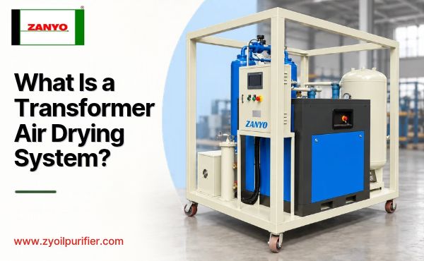
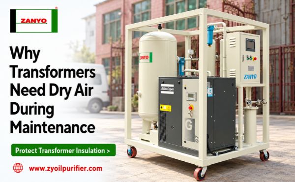
| Transformer dry-air system | Incoming air | Protect insulation during exposure or backfill | Does not evacuate tanks or clean oil |
Some multifunction machines provide auxiliary evacuation or filling modes. Buyers should still verify each function separately. Vacuum available inside an oil-treatment chamber does not prove that the same machine can evacuate large transformer tanks at the required speed.
What to Include in Procurement Specifications
Requests for quotation should identify transformer volumes, starting conditions, permitted pressure limits, treatment time, hose layout, site altitude, ambient range, electrical supply, and mounting preference. Also request pump curves, booster controls, connection sizes, gauge and calibration details, included hoses, weather protection, spares, manuals, training, and commissioning scope.
Conclusion
Reliable transformer evacuation systems are balanced combinations of pumps, controls, instruments, connections, and field procedures. The strongest specification describes required performance at transformer tanks, the conditions under which it must be achieved, and the acceptance method that will be used.
Before comparing prices, buyers should prepare a written duty sheet and confirm transformer-specific limits with manufacturers or asset owners. This prevents oversized pumps from being connected through undersized lines, protects transformers from unsuitable vacuum procedures, and makes supplier proposals easier to evaluate on equal terms.