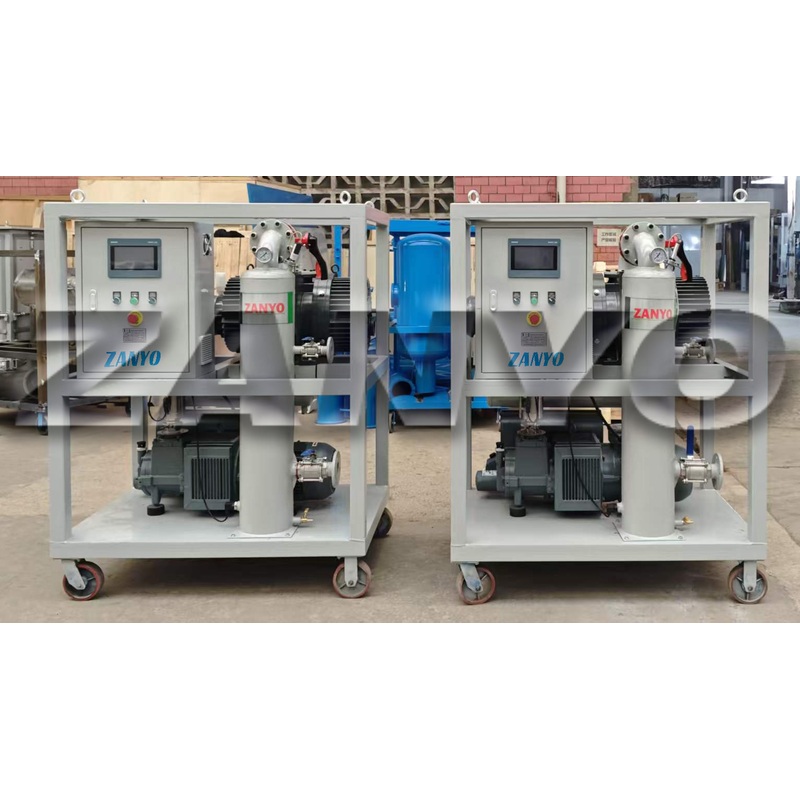
Transformer vacuum pumping systems remove air, water vapor, and gases released from internal surfaces before transformer filling, installation, or approved drying work. They first remove the large volume of atmospheric air, then continue pumping as moisture evaporates and gases leave cellulose insulation and internal components. The process prepares sealed transformer tanks for vacuum treatment or vacuum filling, but reaching low pressure alone does not prove that the insulation is dry.
Vacuum performance depends on the entire path between transformer tanks and pumps. Pump capacity matters, but hoses, valves, leaks, temperature, moisture load, and gauge location can have equal or greater effects on actual pump-down time.
What Happens Inside Transformers as Pressure Falls?
At the start of evacuation, pumps mainly remove free air from transformer tanks and connected pipework. Pressure usually drops relatively quickly because the gas load is large but easy to move.
As pressure continues to fall, the process changes. Air trapped in winding spaces, insulation structures, radiators, and pipework expands and moves toward the vacuum connection. Moisture on internal surfaces begins to evaporate more readily because water boils at lower temperatures under reduced pressure. Cellulose insulation may also release absorbed moisture, although this is slower because water must diffuse through solid material before pumps can remove it.
This explains why pressure reduction normally becomes slower during later stages. A stable pressure plateau does not have only one cause. It may indicate continued water-vapor release, small air leaks, restricted piping, closed or partly open valves, insufficient pumping speed, or several of these conditions together.
How the Main Components Work Together
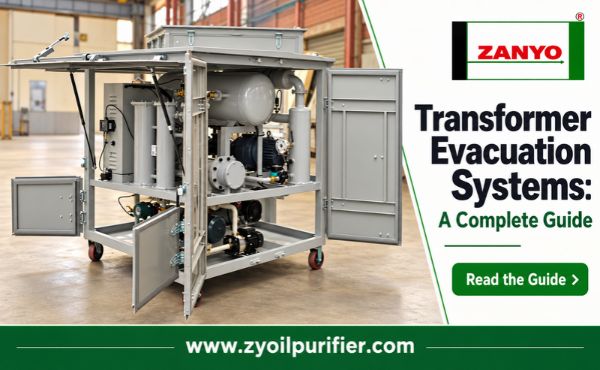
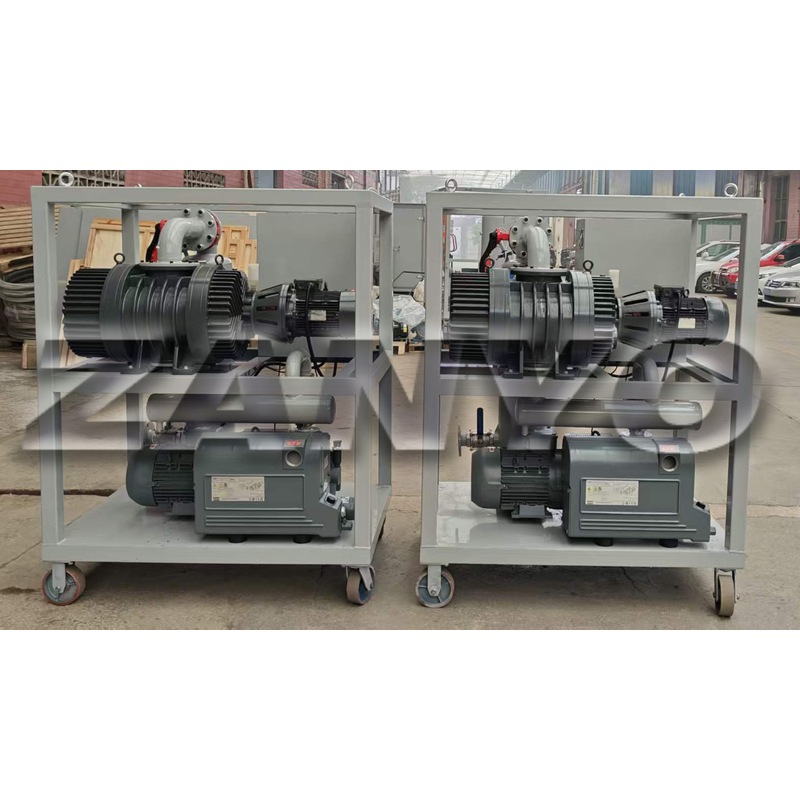
A transformer vacuum pump system is more than a pump connected to a tank. Each component affects the usable pumping speed and process reliability.
| Component | Main function | Important operating consideration |
|---|---|---|
| Backing pump | Removes initial air and discharges gas to atmosphere | Must handle the expected gas load throughout rough evacuation |
| Roots booster | Increases pumping speed within its approved pressure range | Requires a compatible backing pump and pressure-difference protection |
| Manifold and valves | Control and isolate the vacuum path | Undersized passages can restrict the entire system |
| Vacuum hoses or pipes | Connect pumps to transformer tanks | Diameter, length, cleanliness, and leakage affect effective speed |
| Vacuum gauges | Measure pressure at selected points | Pump-side readings may not represent tank pressure |
| Traps and separators | Capture condensate or protect pumps where required | Must be drained, cleaned, and sized for the expected vapor load |
| Check valves and interlocks | Prevent unsafe operation or reverse flow | Control logic must match the selected pump combination |
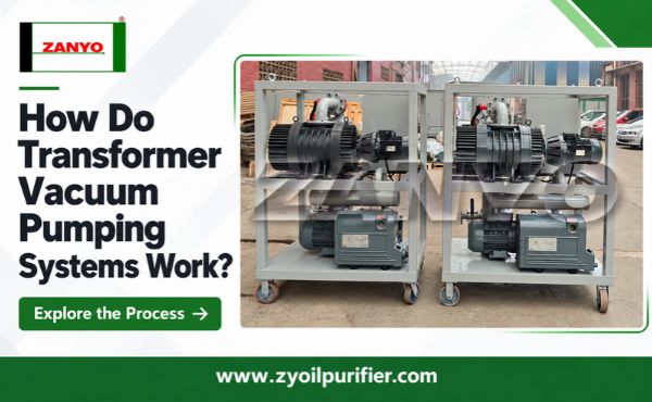
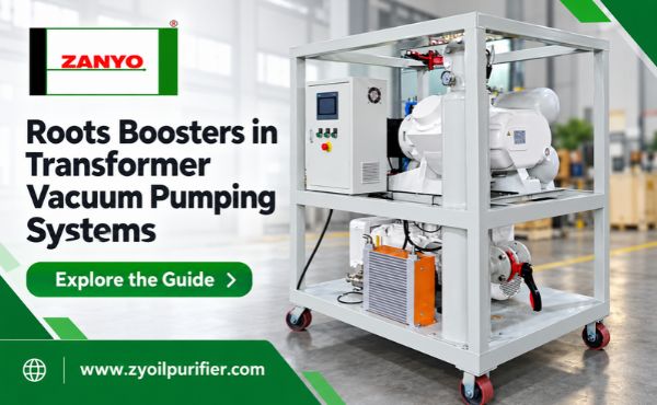
Backing pumps, often called roughing pumps, start the transformer evacuation process and can operate across the initial pressure range. Systems intended for larger tanks or shorter processing windows may add Roots boosters. Boosters move large volumes of gas efficiently at lower inlet pressures, but they generally depend on backing pumps to manage their outlet pressure and discharge gas toward atmosphere.
The Transformer Evacuation Process Step by Step
Before connecting any equipment, technicians must confirm that transformer tanks and connected accessories are approved for the planned vacuum. Some components may need isolation or separate handling. The transformer manufacturer’s instructions and the asset owner’s procedure take priority over generic practices.
The typical operating sequence is:
- Inspect transformer seals, temporary joints, valves, hoses, pump fluids, gauges, and the electrical supply.
- Connect clean, correctly sized vacuum lines and install gauges at locations that show meaningful system and transformer pressure.
- Start the backing pump and open valves in the approved sequence to begin controlled rough evacuation.
- Start the Roots booster only when its control system, bypass arrangement, or permitted inlet condition allows safe operation.
- Track pressure, temperature, motor load, and the rate at which pressure changes rather than watching only the final reading.
- Continue treatment for the time and conditions specified by the approved transformer procedure.
- Isolate the system and perform the required vacuum-hold or pressure-rise assessment.
- Continue to vacuum filling, controlled dry-air backfilling, or shutdown without allowing humid ambient air to enter untreated.
Operators should never assume that the same sequence or endpoint applies to every transformer. Tank strength, insulation condition, oil type, accessories, temperature, and maintenance objectives can change the required procedure.
Why Actual Pump-Down Time Differs from Calculations
Simple calculations based on tank volume and pump displacement are useful for early equipment sizing, but they describe ideal gas removal. Field systems face additional loads and restrictions.
Long or narrow hoses reduce conductance, which means the effective pumping speed at transformer tanks may be far below the pumps’ rated speed. Elbows, valves, adapters, contaminated filters, and small transformer ports create further resistance. A powerful pump cannot move gas through restricted connections faster than those connections allow.
Leakage produces a continuous incoming gas load. Large leaks may prevent initial pressure reduction, while small leaks often become more apparent at lower pressures. Moisture and other gases released from insulation can resemble leakage because both cause pressure to fall slowly or rise after isolation.
Gauge location also changes what operators see. Strong vacuum at pump inlets can coexist with significantly higher pressure inside transformers when connecting lines are restrictive. For important jobs, comparing pump-side and transformer-side readings helps separate pump limitations from connection problems.
| Observed pressure behavior | First areas to investigate |
|---|---|
| Slow reduction from the beginning | Pump direction and condition, major leaks, valve positions, blocked or undersized lines |
| Normal early reduction followed by a plateau | Water-vapor load, small leaks, line conductance, booster operation |
| Good pump-side reading but poor tank reading | Hose, valve, manifold, or transformer-port restriction |
| Fast pressure rise after isolation | External leaks, leaking valves, trapped volumes, or continuing outgassing |
These patterns guide troubleshooting, but they do not replace proper leak testing or transformer-specific acceptance criteria.
Common Errors That Reduce Vacuum Performance
Other frequent errors include using small flexible hoses, locating gauges only on pump skids, starting unprotected boosters against excessive pressure differences, and performing hold tests while temperatures are changing rapidly. Venting evacuated transformers with untreated ambient air can also undo moisture-control work within minutes of completing the process.
Another important limitation is that measured absolute pressure is not a direct measurement of moisture inside cellulose. Transformer vacuum pumping supports moisture removal, but severely wet solid insulation may require a dedicated drying process using controlled heat, circulation, monitoring, or extended treatment.
Conclusion
Transformer vacuum pumping systems work by progressively removing free air, released gases, and water vapor through a controlled pump train. Reliable results require correctly matched pumps, low-restriction connections, meaningful gauge locations, leak control, and a procedure appropriate for the transformer.
Instead of asking only how deep a pump can pull, buyers and maintenance teams should ask how much effective pumping speed reaches the transformer, how the system handles vapor loads, how performance is measured, and what conditions define acceptance. Those questions reveal whether vacuum equipment can perform the required job outside factory test conditions.